NEMA Wiring Diagram Manual for Electrical Specialists
Nearly 70% of the electrical failures within facilities result from poor wiring methods. These figures underlines the requirement of adhering to established protocols, spotlighting NEMA wiring diagrams’ significance for electrical specialists. By means of these schematics, wiring arrangements that fulfill both performance efficiency and optimal security criteria are delineated.
The purpose of this guide is to arm electrical practitioners with comprehensive insights into NEMA standards. Stressing the importance of proper electrical setups is crucial. By learning these rules, practitioners can significantly cut the chance of incidents and guarantee they adhere to safety protocols backed by Installation Parts Supply. Knowledge in l 14-30 plug is essential whether creating modern networks or repairing existing ones, as it improves the capability to deliver reliable and consistent electrical answers.
Primary Conclusions
- NEMA wiring diagrams are crucial for maintaining electrical protection and adherence.
- Proper wiring practices can minimize electrical issues significantly.
- Grasping NEMA norms enhances the effectiveness of electrical setups.
- Installation Parts Supply encourages compliance with regulatory standards in electrical tasks.
- NEMA diagrams accommodate a broad spectrum of functions across various industries.
Comprehending NEMA Standards and Their Importance
NEMA criteria are pivotal in the electrical field, steering safety and performance meticulously. Developed by the National Electrical Manufacturers Association, they establish pivotal benchmarks for designing, evaluating, and labeling electrical equipment. Such measures guarantee standardization and dependability across all electrical configurations, which is priceless.
Identify the NEMA Criteria?
NEMA categories differ from levels 1 to 13. Each level delineates the conditions required for electrical apparatus to operate optimally. Such as, NEMA 1 offers fundamental indoor security but is missing dust protection. On the other hand, NEMA 4 ensures appliances is sealed, a requirement for surviving considerable water exposure. Comprehending these designations is key in selecting proper appliances.
Why NEMA Norms Matter for Electrical Protection
The role of NEMA standards in guaranteeing electrical protection is substantial. They play a significant part in minimizing shock risks, equipment failures, and burn risks. Accurate adherence to NEMA ratings empowers appliances to perform reliably under certain environmental conditions. For external application, NEMA 3 ratings offer protection against the weather, safeguarding the apparatus from inclement conditions like downpour and snow. In regions susceptible to explosions, classifications such as NEMA 7, 8, and 9 are critical for ensuring protection.
Implementations of NEMA Norms in Wiring Drawings
The use of NEMA norms in wiring schematics is essential for safe, effective electrical systems. These diagrams utilize consistent symbols and layouts derived from NEMA standards, streamlining the comprehension of complex electrical configurations. Such standardization is beneficial. It encourages clarity, uniformity, and minimizes confusions, thus improving electrical security across domestic and commercial sectors.
NEMA Wiring Diagram Basics
NEMA wiring diagrams are crucial for electrical professionals, making complicated junctions unambiguous. They detail the connections and elements in various installations. By grasping the elements, kinds, and symbols of NEMA schematics, electricians can boost their performance in setups and maintenance.
Components of NEMA Wiring Schematics
NEMA diagrams comprise crucial components for distinct electrical configurations. You’ll find wiring endpoints, connectors, and additional equipment for safe linkages. Each piece ensures energy is allocated optimally, complying with safety guidelines.
Types of NEMA Wiring Diagrams
NEMA uses different schematics, like connection diagrams and circuit designs. Such diagrams outline device relationships, while layouts display current flow. Choosing the correct schematic aids in diagnostics and deployment.
Common Icons Used in NEMA Wiring Diagrams
Notations in wiring diagrams are crucial for unambiguous clarity. They represent controls, circuits, and couplers. Understanding these symbols aids crews interpret schematics accurately. Such practice ensures configurations comply with NEMA criteria.
NEMA Wiring Diagram Attributes
For electrical professionals, comprehending the key elements of precise electrical wiring diagrams is essential. These schematics provide both lucidity and completeness, synchronizing configurations with NEMA norms. They necessitate accurate annotation and scaling to minimize installation errors. This fosters a protected and optimal working environment.
Primary Attributes of Correct Electrical Wiring Diagrams
Correct electrical wiring diagrams are indispensable in electrical initiatives. They embody key attributes such as:
- Lucidity: Diagrams must be unambiguous, minimizing errors in understanding.
- Completeness: They need to contain all vital parts, linkages, and electrical classifications.
- Standard Compliance: Following NEMA norms is non-negotiable for guaranteeing protection and functionality.
- Thorough Annotation: Unambiguous annotations on each element are fundamental for understanding and avoiding mistakes.
- Correct Scaling: The scales should reflect the real setup to portray the system correctly.
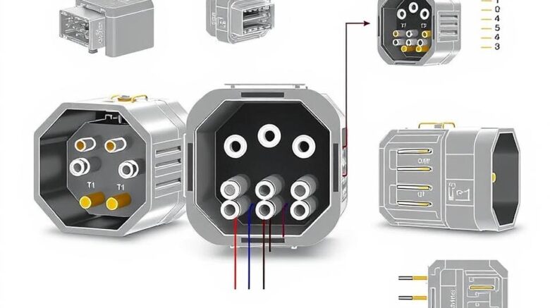
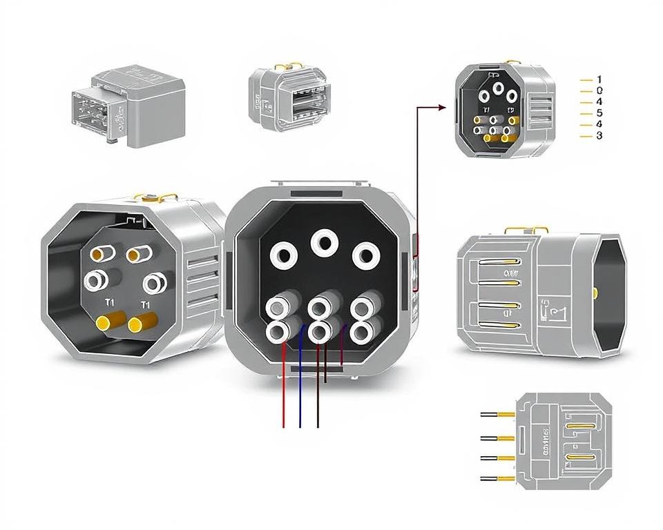
Comprehending NEMA Connector Layout
The insight into NEMA connector configuration is critical for establishing correct connections in electrical networks. Awareness of distinct pin setups maintains safety and equipment performance. There is a variety of NEMA connectors, intended for different voltage levels and flows, including:
| Connector Model | Amperage Rating | Voltage Rating |
|---|---|---|
| L5-15 | 15A | 125V |
| L5-20 | 20A | 125V |
| L14-20 | 20A | 125/250V |
| L1430C | 30A | 125/250V |
| L620C | 20A | 250V |
| L1430C | 30A | 125/250V |
| L630R | 30A | 250V |
Grasping NEMA coupler pinouts is crucial for reliable linkages, boosting performance. It’s imperative to match connectors with appliances properly using locking or linear blade types, to prevent safety risks.
NEMA Appliance Wiring
NEMA device wiring includes multiple configurations for protected electrical device linkages. These rules guarantee that equipment integrate securely, minimizing hazard. Grasping the different NEMA appliances and their wiring is essential for technicians.
Multiple Categories of NEMA Appliances
NEMA classifies appliances by type based on voltage levels and flow demands. Key configurations are:
- 2-Pole, 2-Wire
- 2-Pole, 3-Wire with Grounding
- 3-Pole, 3-Wire
- 3-Pole 4-Wire Grounding
- 4-Pole 4-Wire
- 4-Pole 5-Wire Grounding
These setups are utilized in domestic settings and factories, supporting 125V, 208V, and 480V.
NEMA Outlet Wiring Explained
NEMA plug wiring differs to accommodate various electrical demands, with rotary-lock types providing consistent junctions in shaky conditions. For example, the L5-15 plug works at 15 amps, typical of commercial locations, whereas the L14-20 is crafted for 20 amperes at 125/250 volts.
The NEMA designation system assists in picking the right plugs, emphasizing features like charge orientation and grounding. Such accuracy guarantees that equipment function safely.
NEMA Outlet Wiring Standards
Proper wiring of NEMA sockets conforms to electrical regulations and safety guidelines. For instance, L530R receptacles are rated for 30 amperes at 125 V, with L630R variants for 250 V. Proper grounding is crucial to dodge electrical mishaps.
Selecting certified NEMA plugs and outlets guarantees secure, regulation-compliant configurations. It’s vital to consult authoritative standards when implementing.
NEMA Motor Wiring and Implementations
NEMA motor wiring is essential in electrical engineering, notably for industrial use. Grasping how NEMA motor configuration works guarantees that machines are integrated for best efficiency. Motors, like single-phase and three-phase types, require accurate wiring to operate securely and efficiently.
Overview of NEMA Motor Wiring
Understanding NEMA motor wiring necessitates knowledge of connections and setups. Nearly all three-phase motors now support dual-voltage, indicating they can run on both low (208-230V) and high voltage levels (460V). Wiring at high voltage results in lower current draw than at low voltage. The benefits of high voltage encompass smaller wires for the input, a major benefit for units over 10 HP.
While both NEMA and IEC devices are utilized in the market, NEMA versions are generally more substantial and priceier than IEC ones for below 100 HP uses. NEMA trips range from size 00 to 9, appropriate for diverse uses. A typical attribute in NEMA trips is a Trip Class of 20, intended to trigger when a motor’s current exceeds 6x the rated current in 10 s.
Choosing the Right NEMA Motor Configuration
Selecting the appropriate NEMA motor arrangement impacts overall performance and security. A typical three-wire control circuit employs three wires for a on/off pushbutton station, facilitating straightforward motor management. Typical three-phase setups include the 12 Lead Dual Voltage and 6 Lead, facilitating Wye and Delta configurations.
IEC motor starters frequently incorporate phase monitoring, boosting safety. They also include modifiable Trip Classes for specific protection in low voltage operations. Additionally, many variants have heat protection, essential for one-phase and Dual Voltage systems.
| Setup Type | Power Type | Amperage | Typical Use |
|---|---|---|---|
| 12 Lead Dual Voltage | Dual Voltage (208-230V / 460V) | Motor size dependent | Wye Start and Delta Run setups |
| 6 Lead | Single/Dual Voltage | 32 amps maximum | Both Wye and Delta arrangements |
| Single Phase | Single-level Voltage | Dependent on adjustment (1-5A) | Dual Speed and Dual Winding setups |
| Delta Connection | Elevated Voltage | Based on configuration | Current Transformers, multiple configurations |
The Bottom Line
Understanding NEMA wiring schematics and standards is crucial for electrical professionals looking to improve their capabilities and adhere to electrical safety norms. These standards guarantee protected and high-performing electrical setups but also avoid dangers associated with incorrect wiring. As mentioned, complying with NEMA norms leads to the augmented functionality of multiple NEMA devices and systems.
For electrical professionals, the availability of high-quality materials can profoundly influence the outcome of their work. Installation Parts Supply offers a vast selection of wiring items aligned with NEMA criteria. This empowers specialists to get vital components for fulfilling these important standards. High-quality materials and profound knowledge of NEMA wiring schematics greatly enhance system safety and performance.
In your journey through electrical installations, always put security and accuracy as a priority. Gaining expertise in NEMA criteria provides the knowledge required to implementing best practices correctly. This ensures that every electrical link established meets superior norms.
Frequently Asked Questions
What are NEMA wiring diagrams?
NEMA wiring schematics illustrate the setups and junctions of NEMA-standard electrical appliances. They follow safety and operational norms established by the National Electrical Manufacturers Association.
Why are NEMA criteria important for electrical safety?
NEMA standards are fundamental to defining safety and performance benchmarks for electrical equipment. These guidelines help electrical experts reduce electric shock, equipment failure, and fire hazards.
What components are essential in a NEMA wiring drawing?
Fundamental parts in a NEMA wiring drawing consist of circuit setups and linkage diagrams. These schematics also feature comprehensive annotations and depict the electrical system’s diverse parts accurately for setups.
Identify the varieties of NEMA wiring drawings exist?
Various NEMA wiring diagrams serve various requirements, including circuitry for power distribution and connector schematics. Every layout serves a specific role in electrical installations.
Which are the typical symbols employed in NEMA wiring drawings?
Standard symbols in these schematics depict toggles, interruptors, receptacles, and additional components. Use of these symbols facilitates unambiguous interaction and correct interpretation of wiring schematics.
Which are the essential attributes of precise electrical wiring schematics?
Precision in electrical wiring diagrams is defined by their lucidity, thoroughness, and clear annotation. They must align with NEMA criteria to prevent faults in deployment.
Define a NEMA connector layout?
A NEMA connector configuration describes electrical junctions at a connector, showing distinct pin roles. This ensures reliable and optimal connections in electrical systems.
Which are the various kinds of NEMA units?
NEMA appliances include various electrical sockets and connectors, like connectors and sockets. They are engineered for various current and power requirements to meet specific usage needs.
Describe how NEMA plug wiring arranged?
NEMA plug wiring hinges on defined ampere and power needs, adhering to safety guidelines and regulatory standards for various electrical uses.
Which standards are there for NEMA receptacle wiring?
Standards for wiring NEMA outlets underline complying with electrical regulations, guaranteeing accurate electrical polarity, and choosing proper wire sizes. This sustains both safety and operation in electrical installations.
Describe how to wire a NEMA motor effectively?
To connect a NEMA motor, one must understand its particular one-phase or tri-phase arrangement. Choosing the correct wiring technique is essential, plus practicing electrical safety for enhanced motor efficiency.
What should I consider when selecting a NEMA motor arrangement?
Choosing a NEMA motor configuration necessitates an assessment of the application’s power needs and performance traits. It’s also crucial to confirm compatibility with pre-existing equipment for reliable operation and protection.